




High-Durability Die Casting Mold Developed for 5G Communication Aluminum Heat Sinks
2026-11-13 16:44
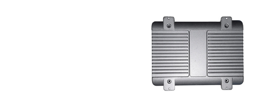
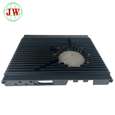
The global rollout of 5G infrastructure has created an unusual tooling problem. Base station aluminum heat sinks are not difficult to cast in principle — they are essentially a plate with a dense array of fins. But in practice, they are among the most punishing parts a die casting mold will ever be asked to produce. Fins are thin, tall, tightly spaced and must be dimensionally consistent across every cavity position, shot after shot, for hundreds of thousands of cycles. The thermal load on the die cavity is severe, the metal velocity is high, and the ejection forces are concentrated on fragile geometry. Conventional molds for this part family have historically failed early — through fin breakage, heat checking on the fin roots, soldering of aluminum to the core inserts, and progressive loss of flatness as the tool distorts.
A newly developed high-durability tooling solution targets exactly these failure modes. Rather than treating mold life as an outcome of steel grade alone, the design approach treats durability as a system property: die steel and heat treatment, thermal management of the cavity block, surface engineering, gating and ejection balance, and a validated maintenance regime all contribute. This article examines each layer of that system and explains why 5G heat sinks demand a different tooling philosophy from general-purpose high pressure die casting.
1. Why 5G Heat Sinks Push Mold Durability to the Absolute Limit
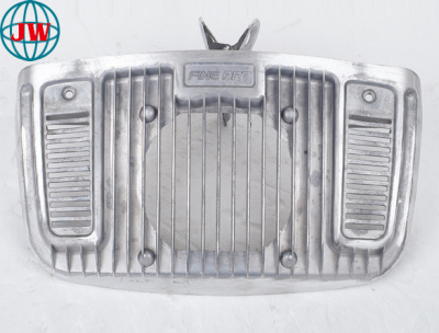
The functional requirement of a 5G heat sink is simple: maximize surface area within a fixed envelope while maintaining flat contact with the RF power module. That requirement translates directly into tooling stress. Fin thickness typically falls in the 1.0–1.5 mm range, fin height can reach 30–50 mm, and fin spacing is often under 4 mm. Aspect ratios of 20:1 or higher are common. Each fin requires a corresponding deep, narrow slot in the die cavity, and each of those slots is a thin, thermally isolated steel finger that must survive repeated contact with 680–720 °C molten aluminum at high velocity.
Three stresses act simultaneously. First, thermal fatigue: the fin-forming inserts cycle between molten metal contact and release-agent cooling hundreds of times per shift, generating heat-checking cracks at the fin roots where stress concentrates. Second, erosion and soldering: high-velocity aluminum impingingon a narrow slot tends to wet the steel surface, and once a solder layer forms, the fin geometry degrades and ejection force rises sharply. Third, mechanical load: ejector pins acting on a thin finned structure create local deformation, and any misalignment accelerates fin cracking.
Add the commercial pressure — 5G orders are large, delivery windows are short, and customers audit flatness and fin integrity closely — and the case for a purpose-built durable mold becomes obvious. A tool that fails at 80,000 shots instead of 200,000 shots does not merely cost a replacement; it costs a production window that cannot be recovered.
2. Die Steel Selection and Heat Treatment: The Foundation of Mold Life
Durability begins with the substrate. For 5G aluminum heat sink tooling, the cavity insert and fin-forming cores are typically produced from premium hot-work die steel such as H13 or improved H13 variants with reduced segregation and controlled inclusion content. Premium-quality ESR (electroslag remelting) stock matters more here than in general work, because fin slots concentrate stress on a very small steel section — a micro-cleanliness defect that would be harmless in a thick block becomes a crack initiation site in a 1.2 mm fin.
Heat treatment is equally decisive and far more frequently compromised. Correct austenitising, adequate tempering cycles and, critically, tempering at a temperature above the expected service temperature all determine whether the steel retains its hardness at the fin root. A tool tempered at 560 °C and run at 300 °C surface temperature will soften progressively; hardness loss then translates into fin deformation and loss of dimensional control. Multi-stage tempering — at least double, preferably triple — reduces retained austenite and stabilises the microstructure against thermal cycling.
For the highest-wear zones, localized treatment pays dividends. Fin inserts can be manufactured as separate cores in a higher-grade steel and mounted into the main cavity block, so that the most highly stressed elements can be replaced individually rather than scrapping an entire insert. This modular approach is now a defining feature of durable heat-sink tooling and lowers total cost of ownership even though the initial tooling price is higher.
3. Thermal Balance and Conformal Cooling at the Fin Roots
Cooling design separates an adequate mold from a durable one. In a finned die cavity, heat concentrates at the fin roots and in the thin core fingers, while the base plate cools comparatively quickly. If cooling is applied uniformly through conventional drilled lines, the result is a strongly non-uniform temperature field: hot fin roots that solder and erode, cold plate areas that cause short shots at the far cavities, and a cavity block that distorts unevenly over time.
Conformal cooling — channels that follow the fin contour at a controlled distance below the cavity surface — attacks this directly. By placing cooling close to the fin root, the local surface temperature can be held within a narrow band, reducing both thermal fatigue amplitude and the tendency of aluminum to adhere. Because the fin slots are narrow, conformal circuits are usually produced by additive manufacturing of the insert rather than by drilling, which also allows the cooling layout to be validated in CAE simulation before the tool is built.
Two further controls complete the thermal picture. Die temperature at steady state should be verified by thermal imaging of the cavity face immediately after ejection, not by thermocouple readings at the manifold; the surface map reveals hot islands that a single probe will never show. Second, the release-agent spray program must be matched to the fin geometry — a heavy, uneven coat insulates the fin slots, raises local temperature and accelerates soldering, while an insufficient coat causes sticking and fin tear-out on ejection.
4. Surface Engineering: Nitriding, PVD and Anti-Soldering Protection
At the interface between steel and molten aluminum, surface engineering determines how long the tool survives. Diffusion treatments such as gas nitriding or nitrocarburising create a hard, nitrogen-rich case that raises resistance to erosion and reduces the chemical driving force for aluminum wetting. For heat-sink cores, a controlled nitrided case depth — deep enough to resist wear, shallow enough not to embrittle a thin fin finger — must be specified rather than left to a generic shop standard.
Advanced protection goes further with PVD coatings: CrN, AlCrN and multi-layer nitride systems applied over a nitrided substrate deliver significantly improved anti-soldering behaviour and lower friction during ejection. These coatings are particularly effective in the fin slots, where the aluminum residence time is longest and the wetting risk highest. Coating durability depends on substrate hardness and surface finish; applying a coating over a poorly polished cavity is wasted investment, since coating failure follows substrate failure.
Die maintenance practice must then protect that investment. Polishing to remove solder build-up should be scheduled on a shot-count basis rather than only when defects appear, and re-coating intervals should be planned into the production calendar. A surface-engineered tool without a maintenance plan reverts to a plain steel tool within a few hundred thousand shots. For 5G heat sinks specifically, records of solder growth on fin cores are the single most useful predictive indicator of remaining tool life.
5. Gating, Ejection and Life-Cycle Validation
Flow design and ejection design complete the durability system, because a well-protected tool can still be destroyed by poor hydraulics or unbalanced ejection.
The gating system for a finned heat sink should deliver metal to the base plate in a controlled, non-turbulent manner, allowing the fins to fill upward with a relatively uniform front. Gate area must be sized so that cavity fill does not require velocities that erode fin slots. Vacuum assistance and well-placed overflows reduce back pressure and cut the incidence of fin tip short-filling and internal porosity at the fin base — defects that are almost impossible to repair and that lead directly to field failures in thermal performance testing.
Ejection must be distributed and synchronised. Because fins are fragile, the ejection force should be carried predominantly by the base plate and by robust perimeter features, with ejector positions verified against the actual sticking pattern rather than the nominal drawing. Any localised pin mark on a fin is both a cosmetic reject and a stress concentration for service.
Finally, a durable mold design must be validated rather than assumed. Life-cycle testing on the actual production press — tracking cavity surface temperature, solder growth, fin dimension drift and flatness across a defined shot count — produces the data needed to set maintenance intervals and warranty tool life. Where available, monitoring of the shot curve and cavity pressure provides early warning of degradation before defective castings reach the customer.
Conclusion
A high-durability die casting mold for 5G communication aluminum heat sinks is not simply a mold made from better steel. It is an engineered system in which premium die steel and disciplined heat treatment are protected by conformal cooling, multi-layer surface engineering and a balanced gating system, and sustained by a maintenance regime driven by measurable indicators. The thinner the fins and the tighter the flatness requirement, the less tolerance the tool has for compromise anywhere in that chain. For foundries serving the 5G infrastructure and thermal management markets, tooling life is now a competitive differentiator: a mold that produces two or three times the shot count before requiring replacement converts directly into delivery reliability, per-part cost advantage and customer confidence.
Related News
More >-
![Which Aluminum Alloy Delivers Better Corrosion Resistance for Electronic Cast Housings?]()
Which Aluminum Alloy Delivers Better Corrosion Resistance for Electronic Cast Housings?
Electronic cast housings serve as critical protective enclosures for consumer and industrial electronics, requiring balanced performance in mechanical strength, thermal conductivity and corrosion resistance. **Die-casting** aluminum alloys are the mainstream choice for mass production. This article compares common grades including ADC12, A380, A356 and A413, analyzing how alloying elements like silicon, copper and magnesium affect anti-corrosion properties. It discusses how mold design, post-treatment such as powder coating and anodizing further improve corrosion performance. Manufacturers need to select alloys according to application environments: high humidity or coastal scenarios prefer low-copper alloys. Reasonable material matching and surface finishing help electronic housings resist oxidation and chemical erosion, extending product service life.
-
![What test reports can you supply for die casting corrosion resistance?]()
What test reports can you supply for die casting corrosion resistance?
Corrosion‑resistance test reports are vital supporting documents for global **die‑casting** component procurement. Manufacturers can supply third‑party lab certificates including salt‑spray, humidity‑heat cycle and chemical‑resistance tests, alongside factory in‑house inspection records. Third‑party reports carry high‑recognition for cross‑border compliance audit, while internal documents work only as auxiliary reference. Test results are heavily affected by **alloy grade**, **surface‑treatment** technology and **tooling** status. It must be noticed that reports apply only to submitted samples and cannot fully represent all mass‑production goods. Buyers are advised to clarify test standards, sample sources and cost‑bearing rules in advance to prevent misunderstanding in **die‑casting** project cooperation.
-
![How to arrange pickup of our finished die casting tooling?]()
How to arrange pickup of our finished die casting tooling?
Picking up finished die‑casting tooling is a high‑risk procedure easily ignored in custom casting projects. Damaged cavities, missing inserts and customs delays often stem from unclear ownership, poor packaging and incomplete paperwork rather than casting defects. This article discusses five key segments: pre‑pickup ownership and technical acceptance, anti‑rust shock‑resistant export‑grade packaging for heavy molds, logistics and lifting selection, cross‑border customs documentation requirements, and post‑delivery unpacking inspection & storage. Operators should check full component inventory, apply cargo insurance and verify the gating system through dry mold test after arrival. Well‑managed tooling hand‑over protects investment and guarantees stable cycle time for follow‑up mass‑production of die‑cast parts.
-
![Which Mold Steel Works Best for Large Integrated Aluminum Die Castings?]()
Which Mold Steel Works Best for Large Integrated Aluminum Die Castings?
This article focuses on mold steel selection for large integrated die casting under ultra-large tonnage high-pressure die casting (HPDC) machines, analyzing extreme thermal and mechanical loads unique to oversized molds. It elaborates five critical performance metrics including mold hardenability, anti-thermal fatigue cracking capacity and anti-aluminum soldering property, and compares three tiers of mainstream hot-work steels (standard H13, ESR upgraded variants, ultra-high hardenability specialized grades). The text explains how poor hardenability triggers penetrating mold cracking and proposes graded zoned steel matching strategies for different production batches, paired with auxiliary thermal balance and surface treatment processes to extend mold service life and cut unplanned downtime for integrated aluminum structural castings
-
![What Surface Finishing Fits Premium Industrial Aluminum Cast Components?]()
What Surface Finishing Fits Premium Industrial Aluminum Cast Components?
Centered on the topic of selecting proper surface finishing for premium aluminum die casting parts, this article analyzes five key dimensions including casting defects from high-pressure die casting, finishing matching rules for different alloy components, pre-processing control of CNC machining allowance, optimization design of die casting mold, and cost-durability comparison of mainstream surface treatments. Common die casting defects like air holes and cold shut severely damage coating adhesion and surface uniformity. Reasonable machining allowance and early mold structural optimization effectively reduce finishing scrap and rework. Six mainstream industrial finishes including powder coating, hard anodizing and PVD have respective applicable scenarios. Matching finishing must combine blank casting quality, service environment and functional demands to guarantee stable high-end appearance and long-term corrosion resistance of precision aluminum cast components.
-
![How Much Does Aluminum Alloy Die Casting Cost?]()
How Much Does Aluminum Alloy Die Casting Cost?
This article analyzes the full cost composition of aluminum alloy high-pressure die casting from five aspects. The total cost includes one-time mold tooling fee, aluminum raw material cost, production processing cost, post-processing & quality inspection cost, as well as logistics and packaging expense. Part complexity, alloy grade, order volume and surface treatment demands greatly affect final unit price. Die casting has high upfront mold cost but low unit price for mass orders. Reasonable structure optimization and bulk procurement can effectively reduce overall procurement cost for die casting projects.
-
![What Tolerance Can Aluminum Alloy Die Casting Reach?]()
What Tolerance Can Aluminum Alloy Die Casting Reach?
This article explores the tolerance capability of aluminum alloy die casting, analyzing key factors including mold accuracy, process parameters, part structure and alloy properties. Typical tolerance ranges vary by part type, with general industrial parts achieving ±0.10mm–±0.30mm, while precision electronic parts can reach ±0.03mm–±0.10mm. Ultra-tight tolerances require secondary machining like CNC finishing. Improving tolerance stability demands mold maintenance, process monitoring and raw material control. Designers should align tolerance settings with die-casting standards and communicate with manufacturers to balance performance and cost, ensuring parts meet assembly requirements while controlling scrap rates.
-
![Where to Find Reliable Aluminum Alloy Die Casting Suppliers?]()
Where to Find Reliable Aluminum Alloy Die Casting Suppliers?
This article explains how to find reliable aluminum alloy die casting suppliers from six dimensions including sourcing channels, qualification verification, technical strength, quality control, delivery capability and trial cooperation. Reliable die casting factories must hold complete certifications, own professional production and testing equipment, and implement full-process quality management. Purchasers can screen suppliers via B2B platforms and industry exhibitions, verify their strength strictly, and confirm reliability through trial orders. Stable process, on-time delivery and sound after-sales service are key to long-term cooperative supply chains.
Get the latest price? We'll respond as soon as possible(within 12 hours)