



Tolerance Standards for EV Aluminum Housing Molds — A Technical Overview
2026-11-02 17:25
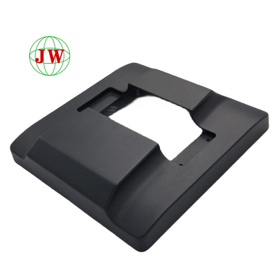
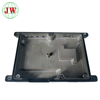
Electric vehicles (EVs) are driving a surge in large, thin-walled aluminum die casting housings — from battery enclosures and motor housings to inverters and power electronic casings. As these components carry tight dimensional requirements and must mate with seals, bolts and cooling channels, the molds that produce them are held to increasingly demanding tolerance standards. Below we break down the key standards, materials, design rules, machining steps and verification methods that define how EV aluminum housing molds are specified, built and validated.
1. The Foundation: Key Tolerance Standards for EV Aluminum Housing Molds
The starting point for any die casting mold is a recognized dimensional standard. The most widely used worldwide is ISO 8062 (and its series ISO 8062-3), which sets general geometric tolerances for castings, complemented by the NADCA (North American Die Casting Association) standards such as NADCA Product Specification Standards for Die Castings. In China, GB/T 6414 mirrors these requirements. These standards classify tolerance grades (e.g. CT7–CT10 for linear dimensions, and tighter grades for machined surfaces) and allow designers to assign achievable values based on part size and wall thickness. For EV housings, critical sealing faces and bolt patterns typically require GD&T (geometric dimensioning and tolerancing) callouts — flatness, parallelism, position and profile — that go beyond the casting-only grades and must be validated on the finished part.
2. Material Selection: How Aluminum Alloys Shape Tolerance Capability
The choice of aluminum alloy directly constrains what tolerance a mold can hold. Common grades include ADC12 (Al-Si-Cu), favored for excellent castability, thin-wall filling and machinability, and A356/A356.2 (Al-Si-Mg), prized for higher ductility, weldability and consistent heat-treatment response. Lower-iron alloys such as ADC6 or A360 reduce sticking but demand careful process control. Because each alloy has a distinct solidification shrinkage and thermal expansion coefficient, the mold must compensate accordingly. For thin-wall EV housings, high-fluidity alloys reduce misruns and shrinkage porosity, while the mold steel — commonly H13 or S136H — must retain dimensional stability at operating temperatures to prevent mold growth that would push tolerances out of spec.
3. Design for Tolerancing: Draft Angles, Wall Thickness and Shrinkage Compensation
Tolerance is largely won or lost at the design stage. EV housing molds typically use a shrinkage factor (commonly 0.4%–0.6% for aluminum) applied to the cavity dimensions to offset contraction on cooling. Draft angles must be engineered into sidewalls — typically 0.5°–1.5° — to allow clean ejection without distorting the part, while uniform wall thickness (commonly 2–4 mm for housings) minimizes differential cooling and warpage. Ejector pin placement, cooling channel layout and gate/runner design all influence residual stress and distortion. Simulation tools (mold flow analysis) are now routine to predict shrinkage, flash and porosity before steel is cut, reducing costly iterations and ensuring the mold delivers the target tolerance on the first trial.
4. Machining and Post-Casting: Closing the Gap to Tight Tolerances
Casting alone rarely meets the tightest EV tolerance requirements, so CNC machining after casting is essential for sealing faces, mounting holes and connector surfaces. The mold must allow adequate machining allowance (machining stock) on critical features while keeping the net shape close enough to avoid heavy cuts that risk warping. Typical machined tolerances reach ±0.05–0.1 mm on critical dimensions, supported by tapping, drilling and de-gating (gate removal) operations. Careful sequencing — machining, then heat treatment or stress relieving where required, then final finishing — prevents distortion that would otherwise accumulate into non-conformance. Deburring and surface finishing on sealing areas further reduce leak paths for the coolant and battery sealing challenges unique to EV housings.
5. Validation and Quality Control: Measuring and Verifying Compliance
Final compliance rests on verification. CMM (coordinate measuring machines) and 3D scanning are used to measure critical dimensions against the GD&T callouts, while leak testing (air or helium) validates the sealing integrity of battery and cooling chambers. X-ray or CT inspection detects internal porosity and voids, and wall thickness gauging confirms uniformity. Documentation per the applicable standard — ISO 8062 or NADCA — with a detailed CMM report accompanies every batch. Any deviation is documented with a deviation notice, so customers receive parts whose tolerance compliance is traceable, repeatable and verifiable before assembly
Related News
More >-
![Innovative Non-Toxic Cookware Revolutionizes Culinary Experience]()
Innovative Non-Toxic Cookware Revolutionizes Culinary Experience
In the dynamic culinary industry, manufacturers are responding to the demand for safe and efficient cookware. Aluminum die-cast and non-stick cookware, alongside BBQ accessories and Teflon pans, are at the forefront. The quest for the best nontoxic nonstick pan has led to revolutionary advancements. Our company leads this charge with premium nontoxic nonstick cookware, boasting durability, safety, and performance. From aluminum die-cast durability to superior non-stick coatings, our products redefine culinary excellence.
-
![How to Solve Shrinkage Porosity Issues Caused by Poor Mold Cooling Design?]()
How to Solve Shrinkage Porosity Issues Caused by Poor Mold Cooling Design?
Shrinkage porosity is one of the most common and destructive defects in aluminum alloy die casting production, mostly triggered by unreasonable mold cooling system design rather than raw material or operational errors. Unbalanced cooling leads to inconsistent solidification rates, residual shrinkage cavities and dispersed pores in thick-walled or hot spot areas, severely reducing product tightness, mechanical strength and yield rate. This article analyzes the internal formation mechanism of cooling-induced shrinkage porosity, summarizes typical cooling design flaws in traditional tooling, and proposes targeted optimization solutions including conformal cooling layout, thermal balance adjustment and process parameter matching. It also introduces professional simulation verification methods to help manufacturers eliminate porosity defects and stabilize casting quality fundamentally.
-
![How Long Is the Typical Lead Time for Custom Aluminum Die Cast Prototypes?]()
How Long Is the Typical Lead Time for Custom Aluminum Die Cast Prototypes?
Custom aluminum **die‑casting** prototype lead time depends heavily on part complexity, drawing stability, selected manufacturing route and post‑processing scope. Standard prototype‑**tooling** plus casting‑sample delivery normally takes 15‑25 working days, while CNC‑machined block samples and 3D‑printed metal samples offer much faster turnaround yet cannot fully replicate real die‑cast mechanical properties. Frequent drawing revisions, casting defects and subcontract‑process backlogs are major delay sources. Buyers should select suitable prototype solutions based on testing purposes, confirm clear timeline definitions, and provide finalized drawings to optimize schedules. Rational arrangement of **CNC** and surface‑treatment demands also helps control overall prototype cycle for cross‑border die‑casting projects.
-
![What is the minimum wall thickness for your die casting parts?]()
What is the minimum wall thickness for your die casting parts?
Minimum wall thickness for die‑casting parts is not a fixed figure. While laboratory‑level thin walls can be achieved, mass‑production needs to consider alloy fluidity, part size, melt flow distance, tooling accuracy and post‑processing such as CNC‑machining. Aluminum alloy commonly adopts 1.2‑1.5 mm as practical minimum wall thickness for stable volume output. Many customers make design pitfalls by copying sheet‑metal standards or ignoring flow distance and wall‑thickness mutation. Early‑stage DFM review with suppliers helps optimize wall‑thickness parameters before mold development. Balancing lightweight demand, filling performance and assembly reliability can reduce defects like mis‑runs and porosity, lower reject rate and avoid costly tooling modification in later project stages.
-
![How to control air bubble defects during die casting process?]()
How to control air bubble defects during die casting process?
Air bubble is a typical defect in die‑casting, caused by trapped cavity air, lubricant vapor and dissolved hydrogen in molten alloy, weakening mechanical performance and triggering failures during secondary machining. This article explains bubble formation mechanism, introduces optimization on tooling including gating system, overflow and vent design, tuning of injection profile and cycle time, molten alloy degassing and scrap management, plus on‑site inspection & preventive maintenance. Vent clogging and turbulent metal flow are major triggers. Mold‑flow simulation supports early‑stage improvement. Full zero‑bubble is not always economical; step‑by‑step troubleshooting and regular mold maintenance effectively reduce bubble reject rate for mass‑production die‑cast components.
-
![What is the lead time for new die casting tooling development?]()
What is the lead time for new die casting tooling development?
This article explains the full lead time range for custom die casting mold development under standard high-pressure die casting, and elaborates five key influencing dimensions. The total cycle varies from 25 to 60 working days, affected by mold manufacturing sequential stages, structural difficulty of aluminum die casting parts, precision standards and reserved CNC machining allowance. Unresolved batch die casting defects such as air holes and flash require repeated mold rectification and extend delivery periods heavily. Drawing revision delays also drag down the whole schedule. Manufacturers can shorten lead time via parallel processing, pre-confirmed technical specs and pre-simulation to reduce post-trial rework, helping buyers arrange reasonable project timelines with proper buffer days.
-
![What steel material do you select for standard die casting tooling?]()
What steel material do you select for standard die casting tooling?
Focused on steel selection standards for standard die casting tooling, this article analyzes five key dimensions: performance requirements for high-pressure die casting steel, mainstream hot-work steel grade comparison, how steel quality suppresses batch die casting defects, steel matching rules based on output and CNC machining allowance of aluminum die casting parts, and cost-service life trade-off for prototypes and mass-production die casting mold. Purified hot-work steel such as ESR H13 and 8407 effectively avoid thermal cracks and sticky aluminum flaws. Low-cost unpurified steel cuts initial tooling expense yet brings frequent rework and scrap loss. Hierarchical steel matching according to order volume balances upfront investment and long-term casting stability.
-
![What Are the Common Defects of Zinc Alloy Die Casting Parts?]()
What Are the Common Defects of Zinc Alloy Die Casting Parts?
This article introduces five common defects of zinc alloy die casting parts, including unique white rust corrosion, internal porosity and shrinkage cavity, surface cold shut, dimensional warpage, die sticking and burrs. Different from aluminum die castings, zinc die castings are more susceptible to white rust and die sticking due to active chemical properties and strong mold adhesion. Most defects result from improper die casting process, poor mold maintenance and incomplete anti-corrosion surface treatment. Targeted process optimization, regular mold upkeep and complete surface protection can effectively reduce defect rate and improve finished product quality of zinc alloy die castings.

Get the latest price? We'll respond as soon as possible(within 12 hours)